GHG System Case
Case specifically for use with the Figaro NGM2611-E13, Adafruit DHT22, AtlasScientific EZO-CO2 sensor, and 6 D cell batteries. Which informs the sensor plate, cable glands, and power supply (length of case and nylon bar).
[TODO: If we removed / generalized the sensor plate and cable glands requirements / instructions this could generally be for a 12” elongated case]: #
Bill of Materials and Potential Supplier or Drawing
| Item | Case Qty | Buy Qty | Supplier Part # / CAD link |
|---|---|---|---|
| 3” ABS Schedule 40 Pipe | 12” | 10’ | Menards 6881155 |
| 3” ABS Hub x Hub Coupler | 2 | 1 | Menards 6881537 |
| -341 EPDM 70A O-ring | 2 | 15 | McMaster-Carr 9557K316 |
| 18-8 Stainless Steel Threaded Rod 3/8” -16 | 6 | 2’ | McMaster-Carr 98804A031 |
| 18-8 Stainless Steel Hex Nuts 3/8” -16 | 24 | 100 | McMaster-Carr 91845A031 |
| 18-8 Stainless Steel Washers 3/8” | 24 | 100 | McMaster-Carr 92141A031 |
| 5” Copper Mesh/Gauze | 20” | 100’ | McMaster-Carr 6361T16 |
| Dow Corning 111 Molykote | Consumable | 5.3 Fl oz | McMaster-Carr 1204K32 |
| Dessicant Packet | 1 | 1000 | McMaster-Carr 2189K34 |
| 11” Cable Ties | 4 | 100 | McMaster-Carr 7130K55 |
| Dome Cap Cable Gland 1/2” NPT .19-.35” w/ O-Ring & Locknut | 2 | 1 | elecDirect RDC13NR |
| 3/4” wide Velcro | 1” | 5’ | McMaster-Carr 9273K13-9273K133 |
| 18-8 Stainless Steel Phillips Flat Head #6 x 1/2” Screws | 6 | 100 | McMaster-Carr 90065A148 |
| 3/4” x 3/4” Nylon Bar | 1’ | 1’ | McMaster-Carr 8732K17 |
| 1/4” Clear Acrylic Lid Plate* | 1 | NA | CAD Drawing 3inch |
| 1/4” Clear Acrylic Sensor Plate* | 1 | NA | CAD Drawing 3inch |
| 1/4” Clear Acrylic Cage Plate* | 1 | NA | CAD Drawing 3inch |
| ABS Cement | Consumable | NA | Menards 6932185 |
| 2D cell battery holder with center mounting points | 3 | 1 | MPJA 36651 BH |
Diagrams

Fig. 1 : Annotated Case Diagram
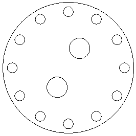
Fig. 2 : Sensor Panel
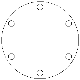
Fig. 3 : Back and Cage Panel
Build Process
Tools & Skills
Fabrication
- Reed TC4QP Tubing Cutter for plastic pipe to cut ABS to length
- Measuring tape
- #2 phillips head screw driver
- Power drill and 1/4” drill bit
Assembly
- 2x 9/16 SAE combination wrench for hex nuts
- Milwaukee 6in Diagonal Cutting Pliers for copper mesh and cable ties
Parts Fabrication
- Cut two 1-21/32” length sections of ABS and 1x 8-1/4” length for the hub inserts and main housing section. When making hub inserts, 20/32 to 22/32 is acceptable, too little won’t hold the o-ring in place, too much won’t compress the o-ring enough to seal properly.
- these lengths may vary depending on brand of coupler, length to cut the ABS sections the O-rings will go around are based on compressing the O-ring around 25% of it’s width of 0.21” = 0.1575” or ~5/32”
- for the NIBCO brand coupler we found a depth of 1 1/2”, so 1 1/2” + 5/32” = 1 21/32”
- we also found the center barrier in the coupler is measured at around 1/4”, 1 21/32” + 1/4 = 1 29/32”, 12” - 2x 1 29/32” = ~8 1/4”
- Mark placement of battery holder screw placements on Nylon bar
- Drill 3/32” pilot holes into nylon bar (for #6 screws) according to battery holder placement centered on bar, then screw battery holder into nylon bar
- Cut 20” of copper mesh
Assembly & Waterproofing
- Attach cable glands
- Apply a small amount of molycote to O-Ring on each cable gland
- Fit cable glands through their respective holes in acrylic sensor plate
- Tighten plastic nut on cable gland gently but firmly to ensure waterproof seal
- Assemble main sonde housing (ABS or PVC)
- Assemble O-Ring ledge
- Find 2 3” pipe D-couplers and 2 1-21/32” sections of 3” pipe
- Apply plastic cement primer to one end of each D-coupler and one end of each pipe section
- Apply plastic cement to primed end of D-coupler.
- Insert primed end of each pipe section into primed and cemented end of each D-coupler
- Tap with rubber mallet to ensure complete insertion, and visually check that that there is no gab between the 1-21/32” pipe section and the insertion ridge inside the D-coupler. This is essential to ensure the correct ledge height for the O-Ring.
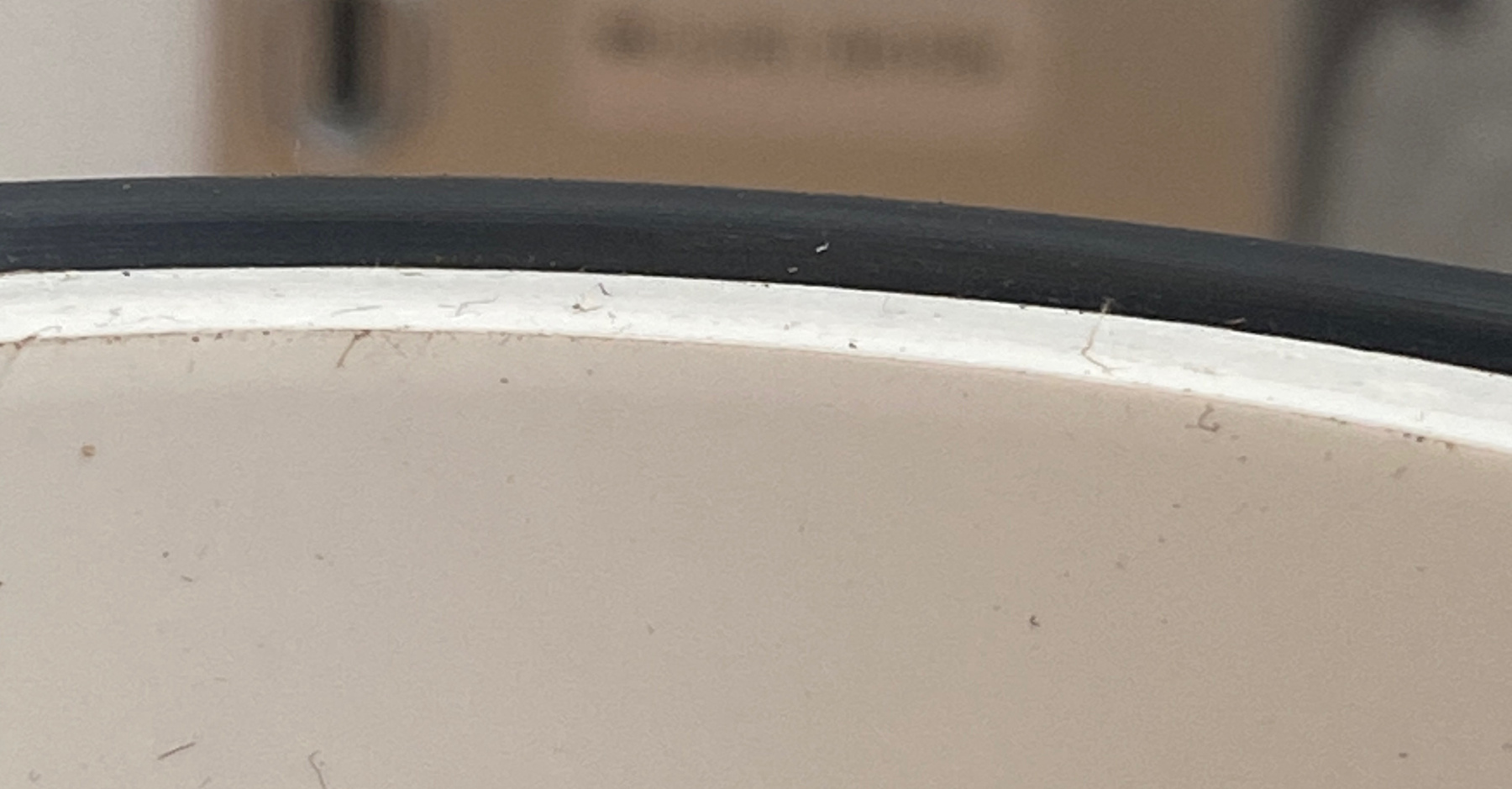
- Check O-ring ledge assembly for correct height.
- Place an O-ring on the ledge created by the inner pipe inserted into the D-coupler in the above steps
- Check that at least 1.5mm of relief exists between the O-ring and the inner pipe segment for the entire circumference of the O-ring.
- The typical reason for a defect at this stage is incomplete insertion of the inner pipe segment into the D-coupler, which can easily compromise waterproofing.
- Correct assembly results:
- Assemble housing body
- Find 2ft length of 3” pipe and 2 O-Ring ledge assembles from (i)
- Check O-ring ledge assembly for correct height
- Checking for a good seal on each O
- Apply plastic cement primer to open end of D-coupler on O-Ring ledge assembly and both ends of 2 ft pipe.
- Apply plastic cement to open and primed end of O-Ring ledge assembly
- Firmly insert primed 3” pipe ends into primed and cemented ends of the D-coupler on each O-Ring ledge assembly.
- Let cure for 3 hours
- Assemble O-Ring ledge
- Build case
- Find 6 threaded steel rods, 24 bolts, 24 washers, 2 O-rings, one sensor plate with cable glands attached, and 2 cage/back plates, and the housing body assembled in (2)
- Build starts from the cage side of the sonde case and proceeds to the back.
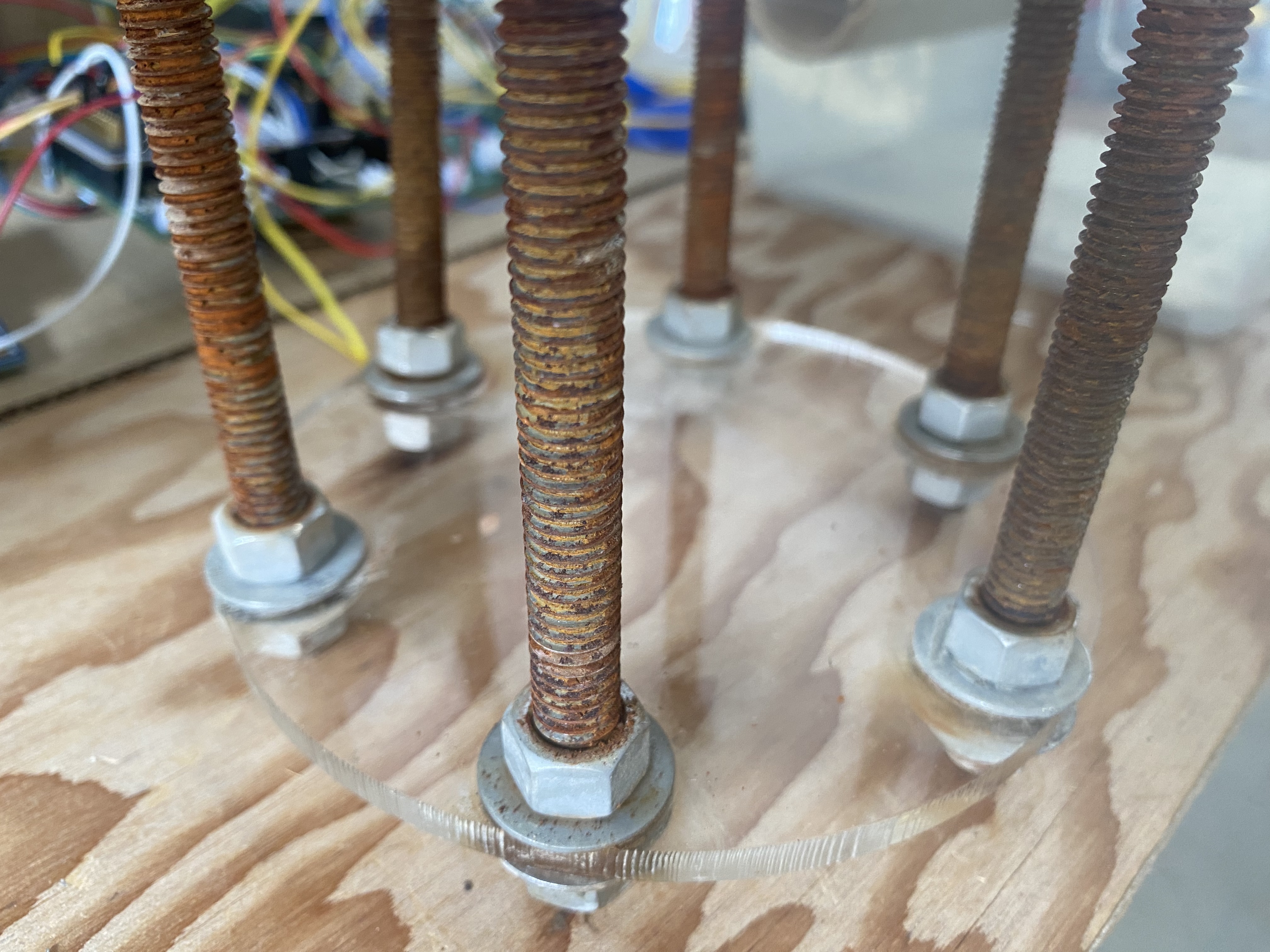
- For each hole in the cage plate, sandwich the plate between two washers and two nuts screwed onto the end of a threaded steel rod.
- Screw a nut about 1 inch onto the rod
- Slide a washer up to the nut
- Slide the cage plate onto the rod
- Slide a washer up to the cage plate
- Tighten a 2nd nut up to the cage plate.
- Repeat for each hole in the cage plate.
- Result looks like this:
- Next, use nuts and washers to create a ledge for the sensor plate to rest on.
- Stand the housing from (2) upright, and turn the assembly from (iii) upside down and place on top of the housing. The cage plate will be facing upward.
- Mark each steel rod, using a marker or masking tape, 1 inch paste the height of the housing. This will be the location of the ledge.
- Take the assembly from (2) back off the housing and place cage plate side down on the table.
- Screw a nut onto each threaded rod up to the point that has been marked
- Place a washer on top of each nut
- Place the sensor plate onto the six rods and allow to rest on the 6 nuts and washers there just installed.
- Visually inspect that the sensor plate is reasonably flat and all six washers are at the same level.
- Now, place O-rings and attach the back plate
- Place an O-ring on the O-ring ledge of one side of the housing from (2)
- Apply a thin layer of molykote to the entire surface of the O-ring
- Place the housing on the sensor plate and between the six rods, with the side with the installed O-ring facing down.
- Place a second O-ring on the O-ring ledge on the other side of the housing
- Apply a thin layer of molykote to the entire surface of the second O-ring
- Place the back plate onto the six rods
- Install a nut and washer onto each rod, and firmly screen them down onto the back plate.
- Check that all six sensor plate nuts are tight, and all six back plate nuts remain tight. Tighten any nuts that appear to be loose.
- Visually inspect O-rings for any signs of improper compression
- Over-tightening: O-ring can squish out of place
- Under-tightening: O-ring is not in contact with acrylic plate in some location
- Attach sensors (This step can also happen before step 5 with some experience doing assembly)
- Disassemble sonde case by removing the back panel, then the housing, then the sensor plate.
- Apply a thin layer of molykote to the inside of the cable glands
- Thread sensor cables (without connectors attached) through the cable glands
- Tighten cable glands to provide waterproof seal
- Reassemble sensor place, housing, and back plate onto the 6 steel rods as in (5)
- Assembly can now be dunk tested for waterproofness
- Internal Assembly
- Ensure sonde case is disassembled
- Cut a 1” section of velcro.
- Attach velcro to back of RRIV datalogger PCA and open area on plastic rod
- Plug battery plug into RRIV datalogger
- Assemble sensor connectors
- Place batter/datalogger assembly upright on top of sensor plate.
- Plug sensors into datalogger
- Reassemble sonde case
- Copper mesh
- Wrap copper mesh around sensor cage
- Secure copy mesh to sensor cage using zip ties